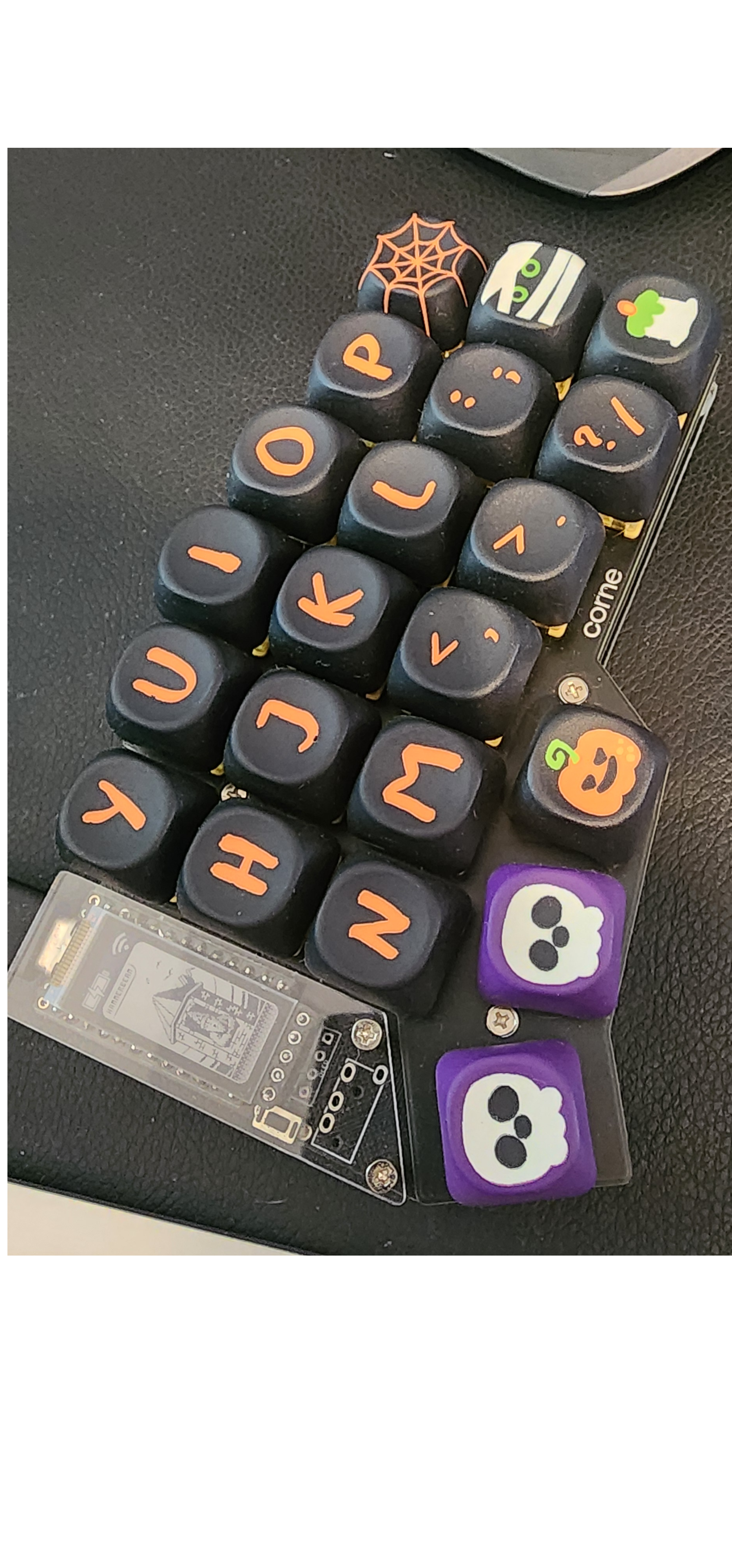
Corne v3 Build
activeA hand-wired Corne v3 split keyboard build — 42 keys, Cherry MX switches, and a custom ZMK layout.
stack
Why
It all started with the challenge of simply being able to type on a split keyboard, especially a reduced layout. I bought a fully built Corne v4.1 and configured it using QMK/Vial. For me, building everything from scratch at that stage made no sense. I didn’t want to go through a complex process only to find out I couldn’t adapt to it. I initially searched for configuration ideas, but none of them really worked for me. Eventually, I stopped looking and started designing my own layout, something that felt intuitive and still somewhat compatible with a traditional keyboard to ease the transition. The transition was painful. I felt like I typed slower than a toddler. After a while, and with a daily routine of about 10 minutes on Keybr, I started improving. I went from typing like a toddler to typing like a granny, still slow, but at least functional. A trick to prevent me from looking at the keyboard was to mix all the keycaps.
Custom Layouts and the Build Decision
Over time, I began to understand the real power of a fully customizable layout. It allowed me to optimize for my own usage patterns. So far, the main results have been better ergonomics and some confused looks from people watching me type. Naturally, I decided to do what any sane and reasonable person would do: build my own keyboard from scratch.
Corne v3 Build
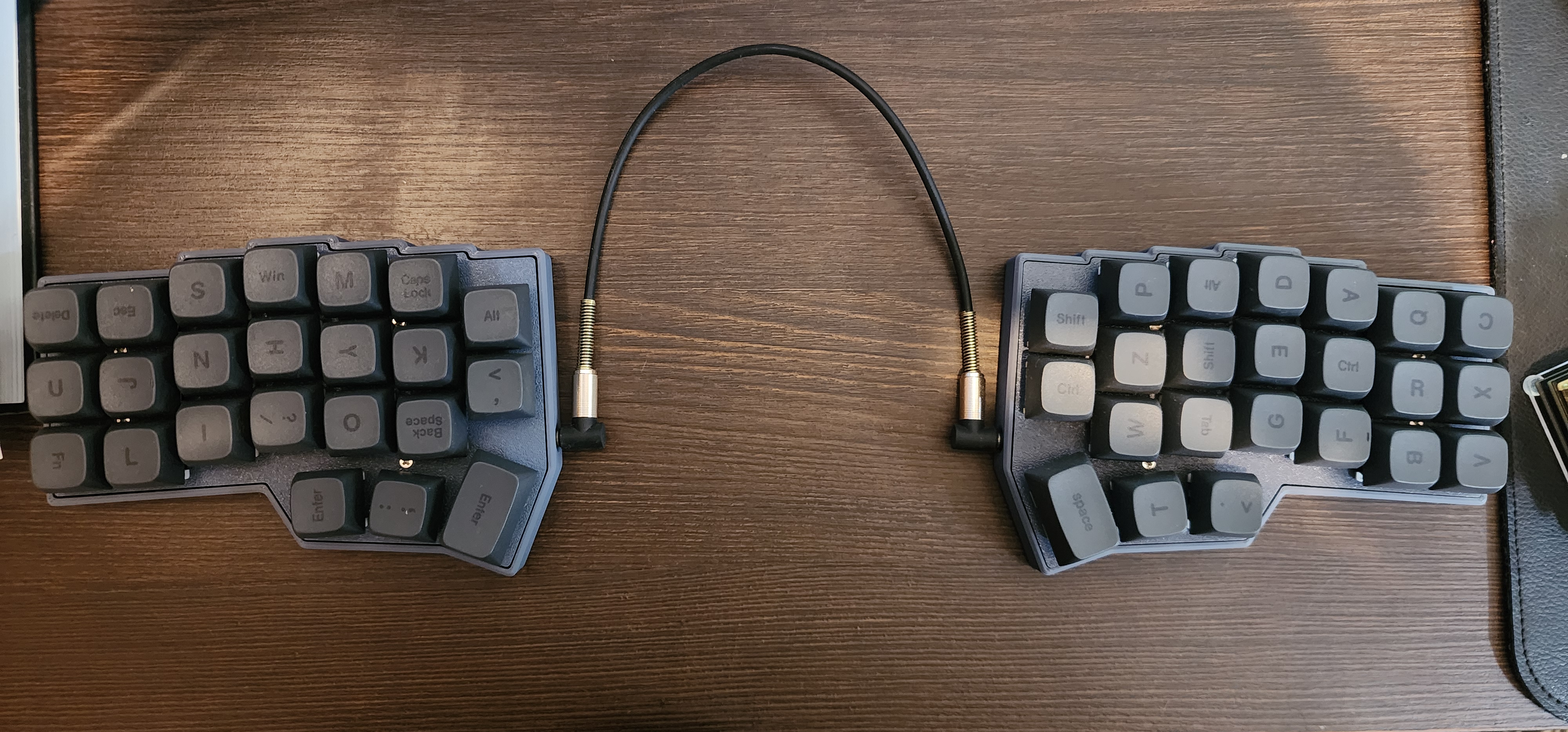
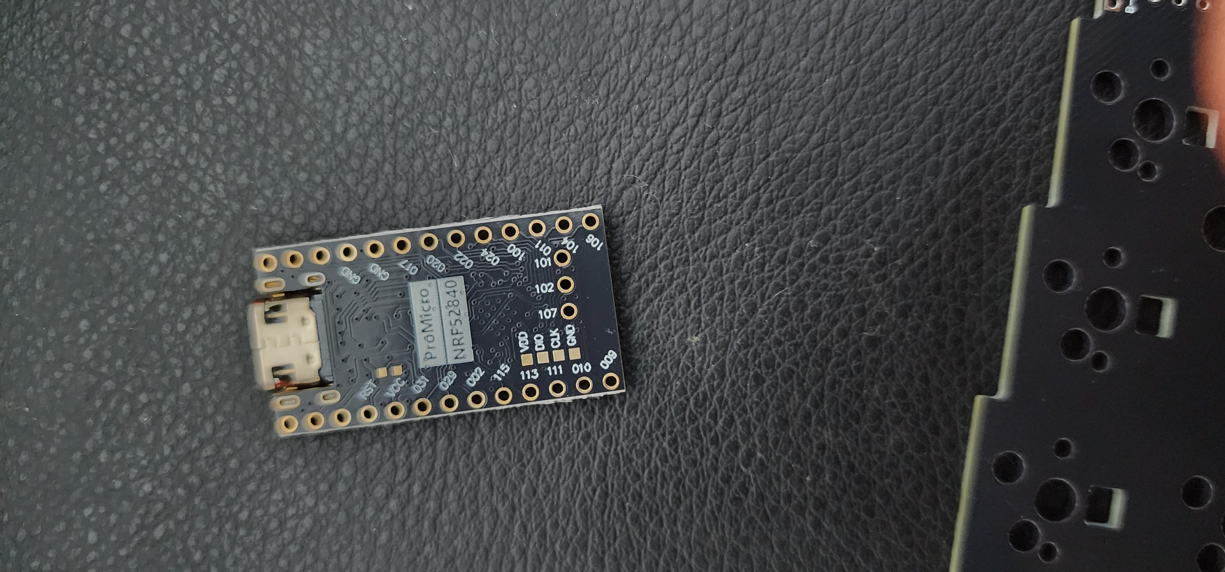
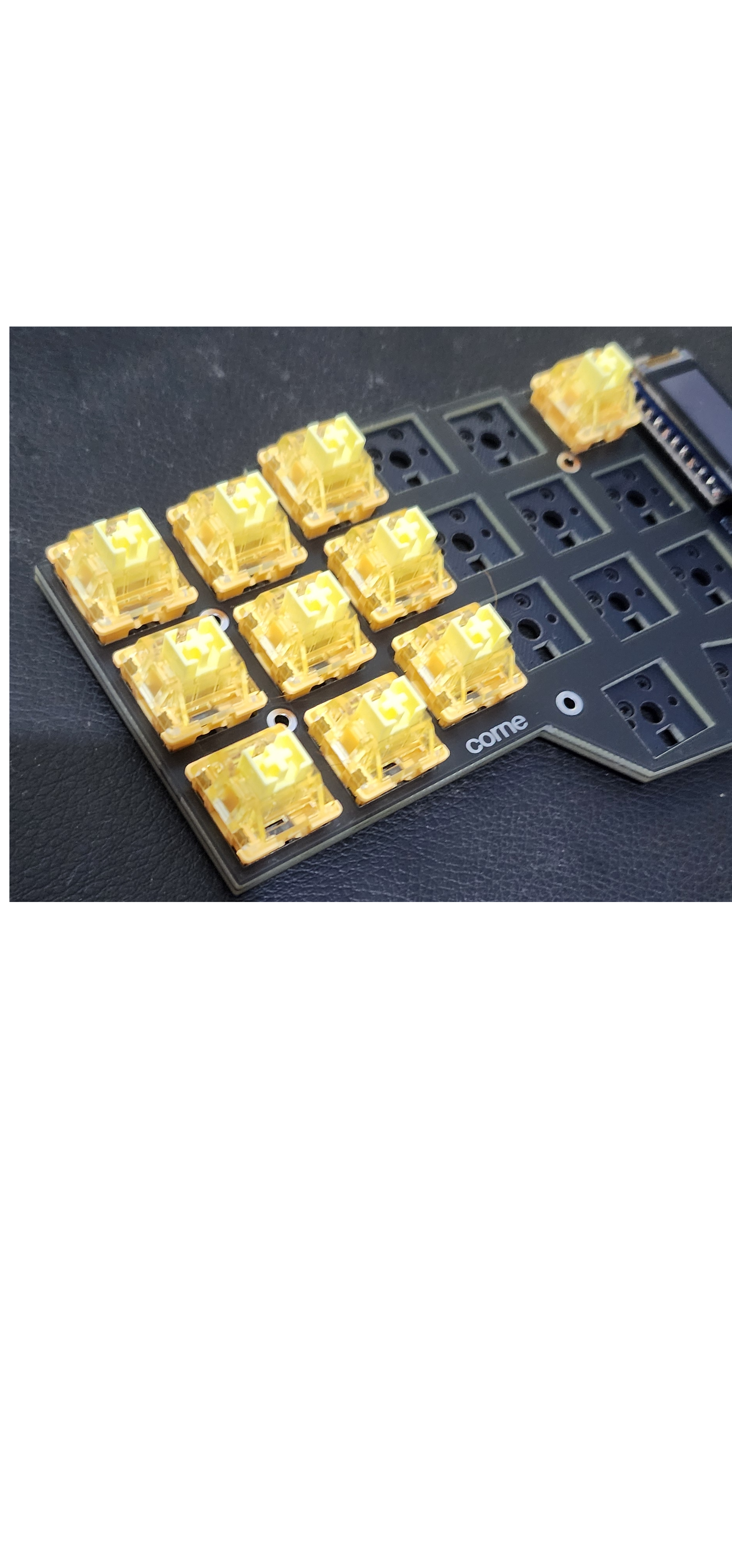
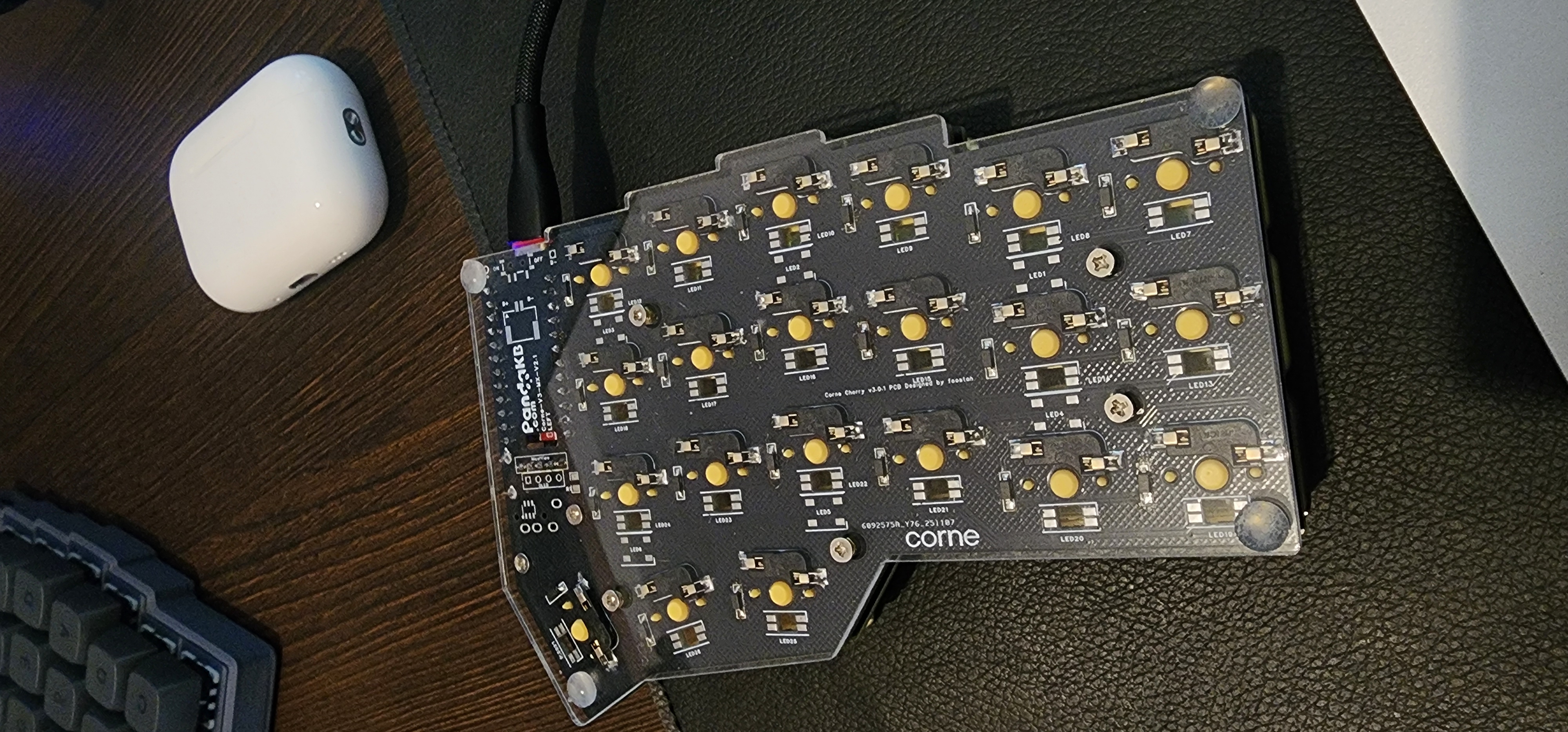
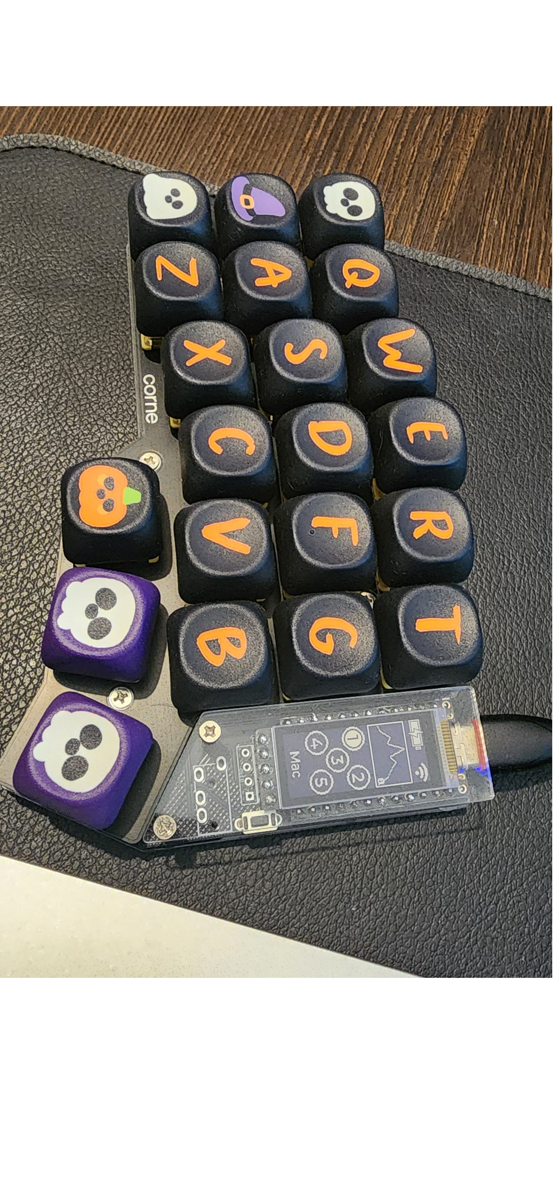
It all starts with the PCB diodes and hot-swap sockets. The soldering can be a huge challenge, the diodes are ridiculously small and must be placed in the correct orientation. However, with some patience and by working slowly, it’s possible to complete it successfully. Soldering kits are quite cheap and useful for other applications, including keyboard maintenance. With those components out of the way, it was time to solder the MCU. I chose the NRF52840, as it is electrically compatible with the nice!nano and much cheaper, so I decided to try it. This MCU also has a Bluetooth component, which makes it easier to switch devices quickly just by pressing a programmed key. Another benefit of this setup is that the main side communicates with the other half wirelessly. This allows both sides to be more physically separated and removes the need for a TRRS cable in the middle. A longer TRRS cable could achieve similar spacing, but it would still occupy the middle area, limiting the placement of other devices. For this build, I opted not to use batteries. I’m still not sure if that was a good or bad decision. Now, both sides need to be plugged into a power source to work, although they don’t need to be connected directly to the device you are using. For example, you can plug both halves into a powered desktop for power, and then switch to another device via Bluetooth without issues. I don’t use this keyboard outside my main setup, and I was hesitant about dealing with battery management, either remembering to charge them or ending up with a dead battery and not using the keyboard at all. In the end, I feel like it may not have been the best decision, but so far it hasn’t caused any major problems. Maybe in the future I design a battery with usb-c connector so I can use as full wireless whenever I need. Just need to keep in mind that doing this requires 3.3V and firmware updates.
Displays
To pair with the MCU, I used a nice!view display. I wanted to make a better use to it instead of the default images and plots. But for me, the customization was way too painful to be worth it. The good part is that if you buy a v2.1 PCB from PandaKB, the nice!view five holes are already there, so there's no need for rewiring the fifth pin if there was only a four hole OLED on the board. The soldering of the MCU and the display are pretty trivial, just align the lables and go for it, they are not as small as the diodes. Keep in mind that there are a bunch of devs out there creating some nice arts for this display, but as they aren't that useful for me, I would not stress over its customization.
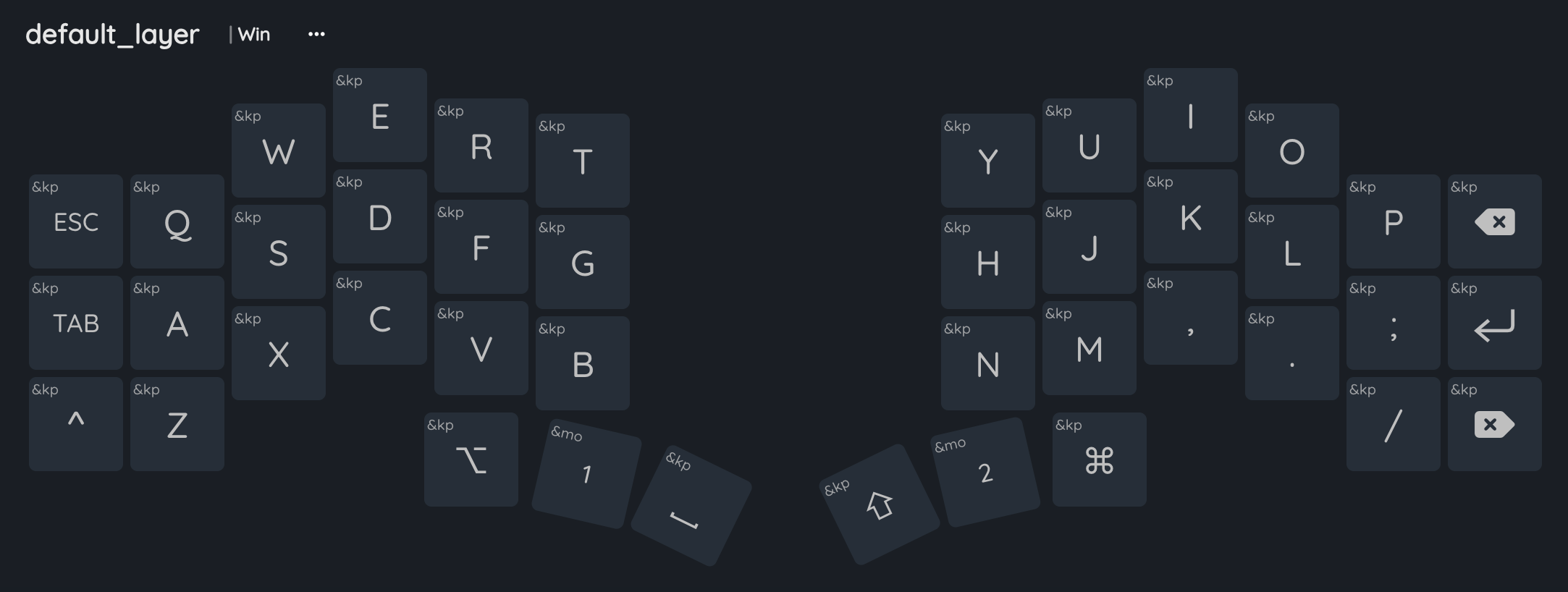
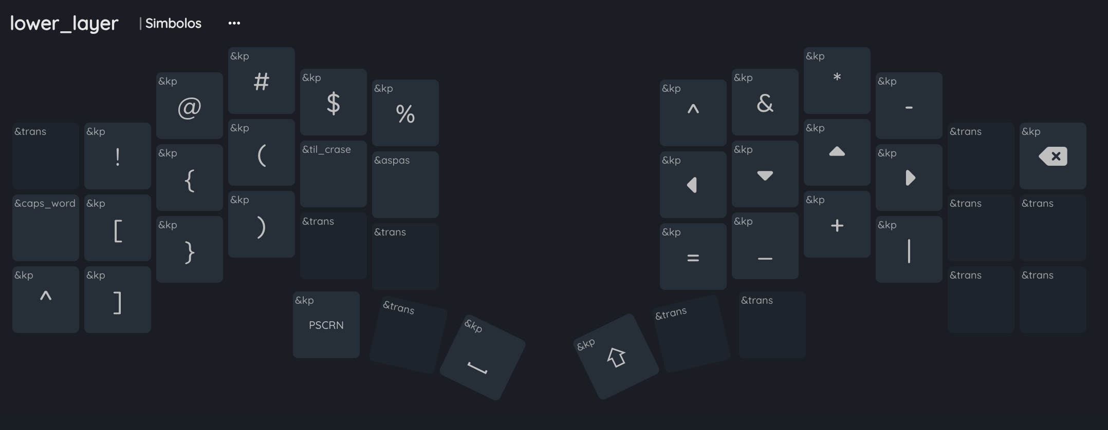
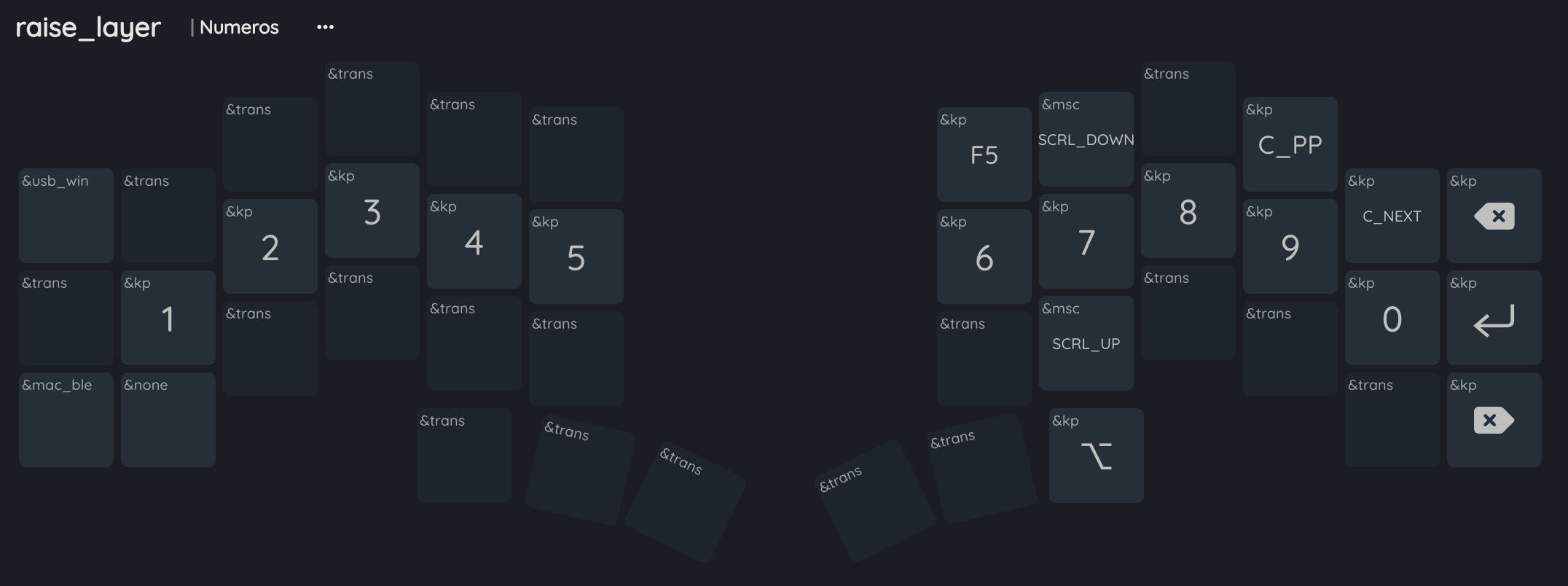
Firmware and Keymap
From that moment, all that was left to do was the firmware. I suffered for a couple of days with manually editing and making commits on the ZMK firmware itself. After a while I found out about the https://nickcoutsos.github.io/keymap-editor/. It connects to your repository and all the edits you do are committed to the .keymap file. It is also handy for exploring functionalities that were somehow hard to find on the official ZMK documentation. As you can see, I kept a bunch of keys like Ctrl, backspace, Enter and some others where they normally would go on a regular keyboard, it really helped with the transition. My second layer has nothing special at all, just two macros for single or double quotes and another for some Portuguese punctuation I use regularly. The third layer has the numbers and some other macros to switch between USB and a Bluetooth device.
Final Thoughts
Is really nice to be able to fully control what you want each key to be and at the same time have some ergonomics on top. The possibilities are endless and my keymap is not a big-brain one, just intuitive and practical setup for me. If you're afraid of soldering or don't like it at all, don't stress over it! Ask or pay someone to do it for you and the fun will be the same. But if you wanna risk it, just watch some youtube tutorials before and practice it somehow, because one error and removing the bad solder becomes a nightmare and possibly a risk for the hardware.
Future Upgrades
One of the possible upgrades is the external battery. As I mentioned, I did not soldered a battery to it internally, so for special moments I might use a power bank module with 5V and usb-c and a thin battery. The porpouse here is to last enough at the same time of being portable. To wrap that build, I would 3D print some silly looking case for each side and have a pretty short way to plug it to the MCU.